Temporary pacing
Indications
Class
Class I
•Is recommended
•Should be performed
Class IIA
•Can be effective/beneficial
Class IIB
•May/might be reasonable
•Effectiveness is unknown/uncertain/not well established
Class III
•Not recommended – ineffective/not beneficial
•Potentially harmful – associated with excess mortality
Bradycardia
SND (prolonged sinus pauses/bradycardia related ventricular arrhythmias/severe symptomatic SBc
•I Acute MI with SND and symptomatic or hemo compromise
•IIA persistent hemodynamically unstable SND (until PPM)
•IIB severe symptoms or hemodynamic compromise (until PPM)
•III minimal/infrequent symptoms with no hemo compromise
•VN block (2nd type II AV block, 3rd AV block, standstill due to AVB)
•I Acute MI and AVB with symptomatic or hemo compromise
•IIA 2nd/3rd AV block with symptoms or hemo compromise
•IIB 2nd/3rd AV block with hemo compromise (until PPM)
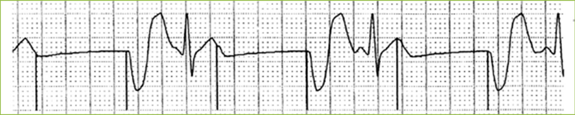
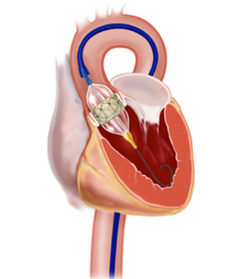
Procedural
•TAVI/BAV – rapid pacing
Other
•Dependent patients for generator changes
•Dependent patients for device extraction

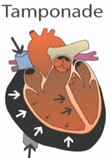
Complications
•Pericardial Tamponade
•Pneumothorax (air between lung & chest –causing collapsed lung)
•Non-pericardial bleeding
•Infection/infective endocarditis
•Diaphragmatic stimulation
•Inadvertent induction of cardiac arrhythmia (VT/VF)
•Asynchrony of chambers (VVI mode)
•Venous thrombosis
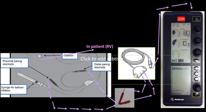
Equipment
•Pacing Box
•Pacing wire
-Swan Ganz balloon tip + red Edwards adaptors
-Pacel (comes with own adaptors)
•Junction connector

Insertion sites


Pacing box

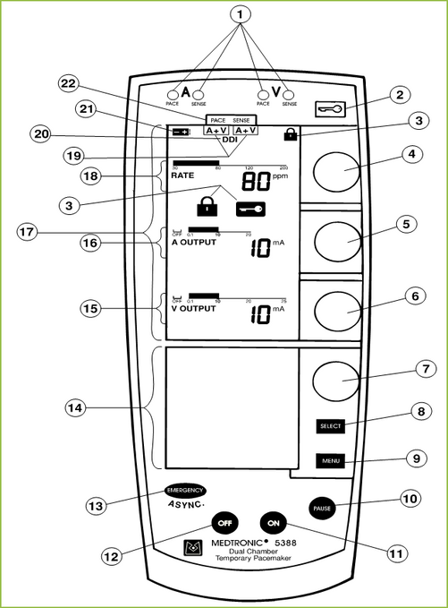
Pacing box 5388
1. Pace/Sense LEDs
2. Lock/Unlock Key
3. Lock Indicators
4. Rate Dial
5. Atrial Output Dial
6. Ventricular Output Dial
7. Menu Parameter Dial
8. Parameter Selection Key
9. Menu Selection Key
10. Pause Key
11. Power On Key
12. Power Off Key
13. Emergency/Asynchronous Pacing Key
14. Lower Screen
15. Ventricular Output Graphics
16. Atrial Output Graphics
17. Upper Screen
18. Rate Graphics
19. Setup Indicators
20. DDI Indicator
21. Low Battery Indicator
22. Setup Labels
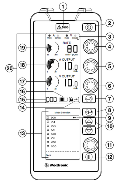
Pacing box 5392


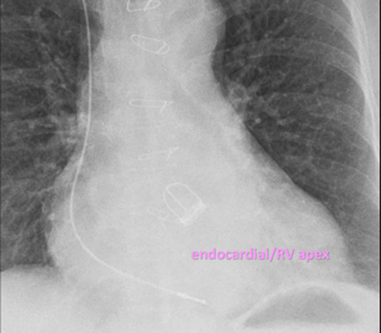
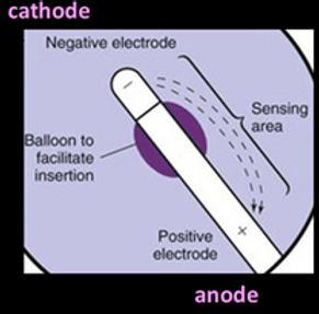
Electrode position
Pacing Modes
Threshold testing
•Threshold is the minimum amount of energy required to capture the heart (result in an evoked response- paced complex on ECG)
•It is necessary to know the threshold to ensure appropriate safety margin is programmed for the output (at least double)
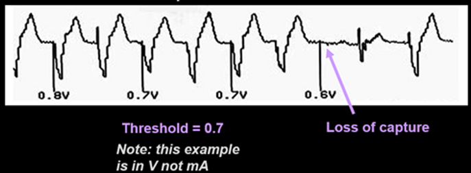
How to perform
1. Set RATE at least 10 ppm above patient’s intrinsic rate.
2. Decrease OUTPUT: Slowly turn OUTPUT dial counterclockwise until ECG shows loss of capture (on ECG).
3. The last output where capture was seen is labelled as the threshold (units mA).
4. Set OUTPUT to a value 2 to 3 times greater than the stimulation threshold value.
This provides at least a 2:1 safety margin.
5. Restore RATE to previous value.
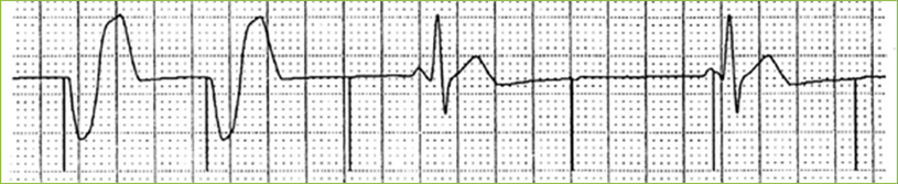
Sensing testing
•Appropriate sensing needs to be determined, to ensure appropriate pacing responses occur
•The size of the intrinsic R wave/QRS complex should be determined to ensure appropriate sensitivity margin is programmed (usually ~half of R wave)

How to perform
1.Set RATE at least 10 ppm below patient’s intrinsic rate and set the OUPUT at sub threshold (below threshold-0.1mV). You will see that the pacing box is flashing sensing in accordance with each intrinsic beat

2. Increase SENSITIVITY: Slowly turn sensitivity dial (in menu section) counterclockwise until flashing in the sensing window no longer occurs. Pacing flashing will then occur at the set pacing rate. Competitive pacing will not occur as the output is set below threshold.

3. The sensitivity value where sensing was last seen is labelled as the sensing threshold or size of the R wave.
4. Set SENSITVITY to a value around half of the sensing threshold value (units mV)
This provides at least a 2:1 safety margin.
5. Restore RATE and OUTPUT to previous values.
Video on testing threshold and sensing testing in a single chamber temp system- > click below link
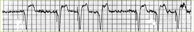
Troubleshooting
Identify the problem
•Loss of capture
•Loss of output
•Oversensing
•Undersensing
Identify Solution and carry out protective procedures
Loss of capture
Possible Causes
•Increased thresold
•Lead moved/dislodged
•Battery depletion
•Fracture lead
•Faulty cable connections
Correct the problem
•Increases output
•Reposition lead
•Replace battery
•Replace lead
•Check/change connections
Loss of output
Possible Causes
•Oversensing
•Pacemaker OFF
•Battery depletion
•Fractured lead
•Faulty cable connections
Correct the problem
•Decrease sensitivity
•Turn pacing box ON
•Replace battery
•Replace lead
•Check/change connections

Oversensing
Possible Causes
•T wave oversening
•Environmental interference
•Fractured lead
•Faulty cable connections
Correct the problem
•Increase sensitivity
•Eliminate interference
•Replace lead
•Check/change connections
Undersensing
Possible Causes
•Decreased QRS size
•Lead moved/dislodged
•Battery depletion
•Fracture lead
•Faulty cable connections
Correct the problem
•Increase sensitivity
•Reposition lead
•Replace battery
•Replace lead
•Check/change connections