


Troubleshooting oversensing
Types of oversensing
Internal (physiological factors)
•Myopotential
•TWOs
•Double R wave counting
•P wave oversensing
•Far field R wave (atrial channel)
External (factors outside the patient)
•Electromagnetic interference
System Related Issue
•Lead/header malfunctions
-Fracture noise
-Insulation breach noise
-Header connector issues
•Air entrapment
•Device algorithms
-minute ventilation
-CLS
Determining oversensing source
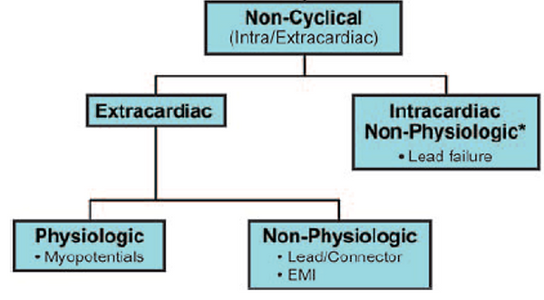
Electrogram (EGM) morphology classification
•Temporal pattern (cyclical vs non cyclical)
•Source type (physiological vs non physiological)
•Source location (intracardiac vs extracardiac)
EGM features
•Noise frequency
•Noise amplitude and variability
•Duration
Source / activity at time of oversensing
Number of affected leads

Internal Causes
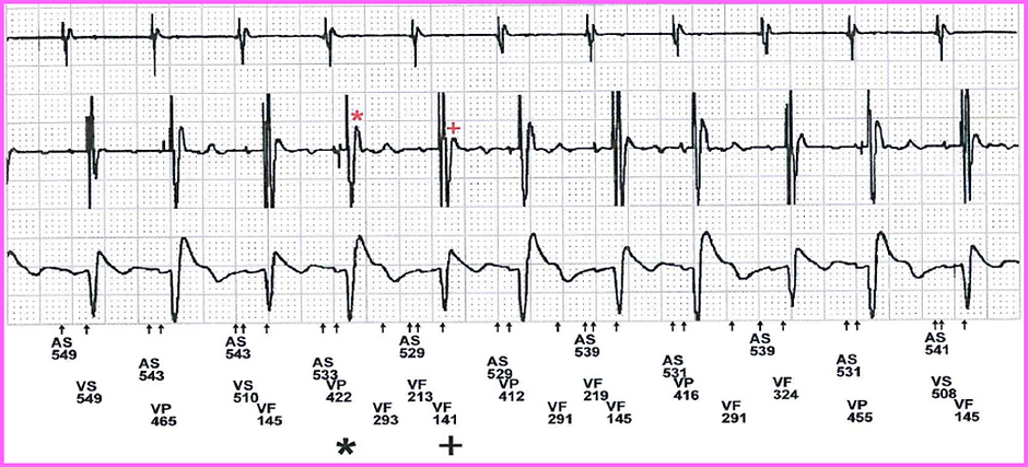
T wave oversensing (TWOS)
Current devices have sophisticated algorithms to minimise TWOS (threshold decays, etc).
May be seen more in particular device manufactures over others due to filter settings
More likely to be seen particular patient groups
Long QT patients
•Prolonged QT may be reversible if caused by metabolic imbalance or medication
Short QT patients
•Tall T waves
May also be seen where there is a transient/persistent drop in R wave
May only be seen in some patients at higher rates
•Treadmill testing has been found to expose TWOS for some patients
Rarely seen, but very difficult to program around
Caution: reprogramming devices may result in risk of undersensing true arrhythmias
•Sensitivity adjustments
•Increasing ventricular refractory period
•Changing sensing vector
-PPM: Bipolar vs unipolar
-ICD: Bipolar vs integrated bipolar
•Threshold decays in some device are programmable
•If only with CRT paced complexes
-can change BiV pacing offsets
-can change LV pacing polarity
•Worst case scenario would be repositioning lead to a different site


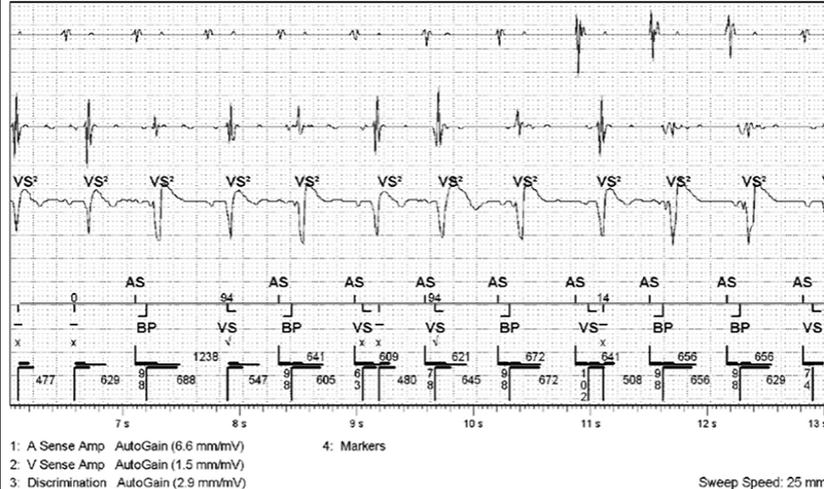
R wave oversensing
Risk of this occurring is typically rare
Characteristic railroad pattern on plot EGM
Most commonly seen in devices where
•Short ventricular blanking periods <120ms
•Integrated bipolar leads
Causes
Ventricular conduction delay
•PVCs / VT
•May be reversible
•Metabolic changes
•Antiarrhythmic drugs
Loss of RV capture
•Poor programming / auto threshold algorithm dysfunction
•Infarction
•Lead failure
•Metabolic changes
•Medications
•Post DCR
P wave oversensing
Would only occur with suboptimal lead position or lead dislodgement
Requires lead reposition
More likely to happen on an integrated bipolar defib lead (note: all Boston devices are programmed as integrated bipolar. This option is programmable in Medtronic devices).

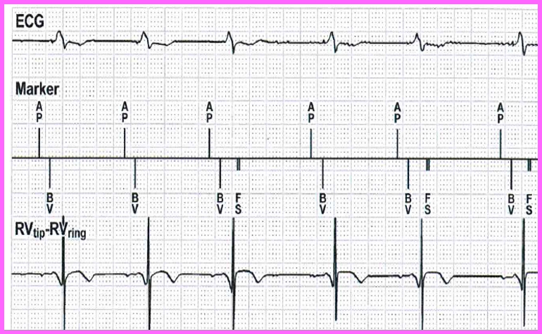
Far field R wave
Common issue where atrial lead senses a far field ventricular signal
It is more likely to occur in the following scenarios
•Unipolar lead sensing
•Very sensitive programming
•Wide electrode spacing
•Atrial lead position closer to the tricuspid valve
Troubleshooting
•Adjust atrial sensitivity (risk of undersensing true arrhythmia)
•Increase PVAB (risk of blanked atrial flutter)

Myopotential / muscle artefact
Myopotentials include diaphragmatic, pectoral or intercostal
20-200Hz frequencies – dominant at 75Hz
Highly variable amplitudes
Provoked by muscle movement and duration consistent with movement
More likely to occur on
•a unipolar lead
•an atrial lead, due to proximity of atrium to pectoral muscle
•subcutaneous or substernal ICDs
Diaphragmatic myopotentials will not be seen on endocardial shock channels
Pectoral myopotentials not recorded on closely spaced bipolar, intact leads


External Causes
Electromagnetic interference (EMI)
EGM characteristics of EMI vary depending on the source of the signal
•Alternating current from line sources shows a characteristic, uniform, noncyclic, high frequency pattern (50 Hz (60Hz in US))
Depending on distance to EMI source, may appear to be more prominent on 1 lead in a multi-lead system
•Differences in electrode surface area
•Interelectrode difference
•Antenna spatial orientation
•Amplifier sensitivity
•Bandpass filters
Diagnosis typically confirmed by history of exposure at episode occurrence.
Overall incidence of ventricular oversensing events is 7.3%
Incidence of inappropriate therapy related to EMI is ~1% per patient per year
Possible Responses to EMI
•Inappropriate inhibition of pacemaker output
•Inappropriate triggering of pacemaker output and inappropriate tracking
•Asynchronous pacing
•Reprogramming – usually back up mode
•Inappropriate initiation of other features; MS or rate drop response
•Inappropriate detection of EMI as a ventricular tachyarrhythmia resulting in ICD discharge
•Inappropriate detection of EMI as a atrial tachyarrhythmia
•Failure to sense VT/VF
Typical causes of EMI
•In hospital
•Diathermy
•Catheter Ablation
•MRI
•Outside of hospital
•Arc welding
•Ungrounded equipment – old washing machines,
•Electric currents in water – swimming pools, old taps


System related issues
Air entrapment
May occur immediately after implant or typically within the 1st few days to weeks of a subcutaneous ICD implant
•Not reproduced with typical manoeuvres
•Manipulation over the substernal subcutaneous pocket has been shown to produce this pattern when air entrapment is present
Temporary issue: air absorbs over time
•temporarily reprogram of sensing vector
To minimize air entrapment several techniques can be employed
•flushing the sternal track with saline
•massaging the skin over the lead
•ensuring proper suturing at the incision site
Artefact typically presents with 2 main features
•Sudden alternation in voltage due to air movement inside the pocket resulting in sharp deflections
•Entraped air insulated the sensing electrode causing wandering or drifting baseline, along with low amplitude signals reslting in oversensing from autogain sensing


Crosstalk
Crosstalk is commonly known when an atrial pace is sensed on ventricular EGM
Can also be seen when 2 devices are implanted which
interact with each other
Most likely to occur with
•High output pacing
•Unipolar pacing
•Proximity of electrodes
-either atrial to ventricular or
-electrodes of different systems
Troubleshooting crosstalk
•Deactivate one of the active systems if device-device crosstalk
•Increase ventricular blanking period (for AV crosstalk)
•Decrease ventricular sensitivity
•Decrease output of crosstalk source
•Reprogram crosstalk source from unipolar to bipolar if applicable


Lead / header malfunction noise
Typical lead malfunctions include
•Lead fracture
•Insulation breach
•Header/connector issue
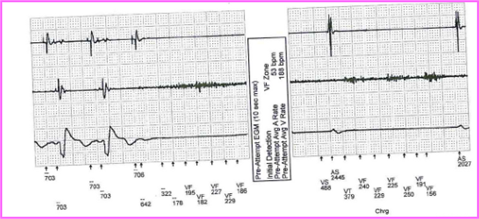
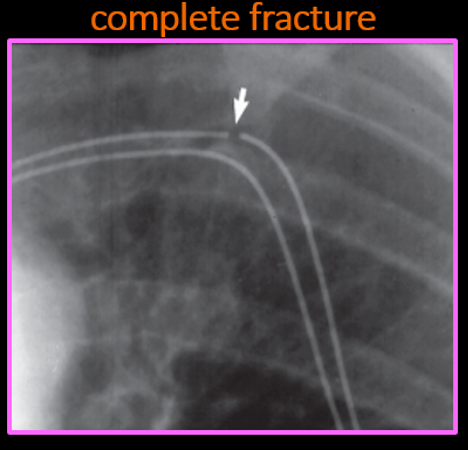
Lead fractures
Lead fractures either present as
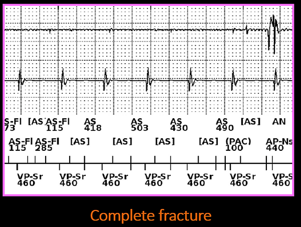
•Complete lead fracture
-No lead function (no shocks/pacing/sensing function)
-Consistent and persistence noise on EGM
•Partial lead fracture
-Intermittent malfunction of the lead
-Intermittent noise, loss of capture, etc
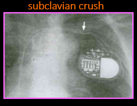
Conductor fractures tend to be located in the origin of venous access or near the can (area of greatest stress; subclavian crush risk)


Fracture & connector issues
Noise intermittent and highly variable
Duration may be associated with movement
Characteristics
•Signals are intermittent & varying in frequency (1-200Hz)
•>1 type of variability in amplitude, morphology or frequency
•Signal amplitude may exceed sensing amplifier range appearing truncated
•At least some signals are non cyclical
•Some intervals are not physiological (<200ms)
•Complete fractures: consistent and persistence noise on EGM
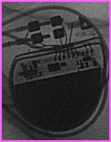
Connector issues
Connector issues may occur if
•the lead is not properly aligned within the header
•There is air in the header (piston effect)
•Blood/fluids caught in the header
Bubbles escape when they produce a threshold pressure on the seal plug, generating a nonphysiological signal
Noise may disappear over time due to pressure being relieved over time
Insulation failure
A breach in insulation may cause current shunting into the tissues and may manifest with low impedances
•impedance of <25 ohms can cause shunt of current into circuitry damaging charging circuit of the device
Oversensing occurs due to signals entering the intact conductor at the point of insulation breach
•EGM patterns vary reflecting the source of the signal
2 types of insulation breach
•Outside in
•Inside out
Outside in abrasions
Often seen near the pocket as a result of friction
•Between the leads
•Between the lead and device or
•the lead and internal structures (first rib, clavicle-subclavian crush)
•Intermittent, high amplitude pectoral myopotentials suggest in pocket, outside in abrasion
Lead on lead abrasion
Also known as “chatter,” “sizzles” or “mirror artefact noise”
A form of crosstalk which suggests insulation breaches if seen in adjacent leads (outside in abrasion)
Artefact produced on each lead reflects the same mirror image (2 active leads)
May only be seen on 1 lead if interaction is with a capped/inactive lead
Radiological assessment of lead integrity and consideration of lead extraction/ replacement
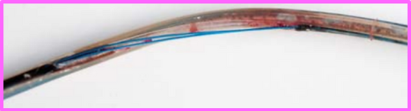
Inside out abrasions
Relative movements of conductor cables in the multi-lumen silicone ICD leads with secondary conductor cable externalisation
As high as 27% of Riata leads have been reported to have had lead externalisation
•However, not all externalised leads have electrical dysfunction
•Those with electrical dysfunction risk of failure of ICD shock
Mechanical interactions between the 2 shock components or pace-sense components
•Riata leads: characteristic spikes on sensing channel
•Ring electrode on shock coil: reports of simultaneous non-physiological signals on the shock and sensing EGMs


Lead noise algorithms
Some devices have alerts for suspected lead noise or try and withhold therapies if suspected noise.
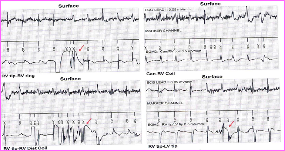
Abbott Secure sense algorithm– vibratory alert (ICDs only)
Fast events detected on near-field EGM (RV ring-RV tip) are compared to far-field EGM (nominal: RV coil-can).
•Correlation: therapy is delivered.
•No correlation: therapy is withheld – Dx as lead noise
Occurs prior to detection
Minimises risk of inappropriate shocks
Medtronic Leaf integrity alert – auditory alert (ICDs only)
If 2/3 of the following events occur, an auditory alert will occur every 4 hours
•>1 NSVT (CL >220ms)
•Abnormal sensing integrity counter (SIC) (>30 in 3days)
•Abnormal RV pacing impedance
The following programming changes will also occur
•VF zone extended to 30/40 (if shorter)
•VT zone extended to 32 beats (if shorter)
•Pre arrhythmia storage turned on for 1 month for VHRs
Medtronic - ventricular lead noise oversensing
Fast events detected on near-field EGM (RV ring-RV tip) are compared to far-field EGM (RV coil-can or SVC-RV coil).
•Correlation: therapy is delivered (<3/12 events).
•No correlation: therapy is withheld – Dx as lead noise
Occurs prior to detection (initial detection only)
Investigating lead noise
Physical movements/arm maneuvers

Impedance testing
•Pacing lead impedance is relatively insensitive to inner insulation failure
•When a HV lead defect is suspected, a full output shock may be necessary to evaluate lead integrity
•Partial defects may not be identified by low energy pulses/regular impedance measurements
Taking a history of activity at time of noise
•Recording the history of when the noise was observed can assist in localising the source of the noise, such as identifying EMI as a potential cause
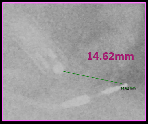
X-ray
•X-ray imaging can be valuable in detecting lead fractures or insulation breaches.
•However, the absence of such evidence on X-ray does not completely rule out lead malfunction as a potential cause.
High output pacing
•High output pacing can be potentially useful when lead defect is suspected
•A polarisation artifact may be inducible in partial fractures that is pulse width dependent

Header/device manipulation
