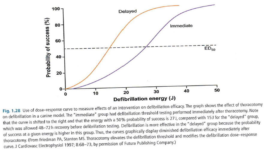
Threshold & dose response curves
Demonstrates the probability of the success of defibrillation with increasing energy.
The slope is characterized by its slope and intercept, and specific points on the curve – ED (energy dose) representing the % probability of successful shock.
Factors adversely affecting defibrillation shift the curve to the right (more energy required).

Threshold & dose response curves
Factors affecting shock efficacy
Fibrillation duration
Degree of ischemia
Potassium accumulation
Distribution of electrical activation at the time of shock
•Vector
•No. leads involved
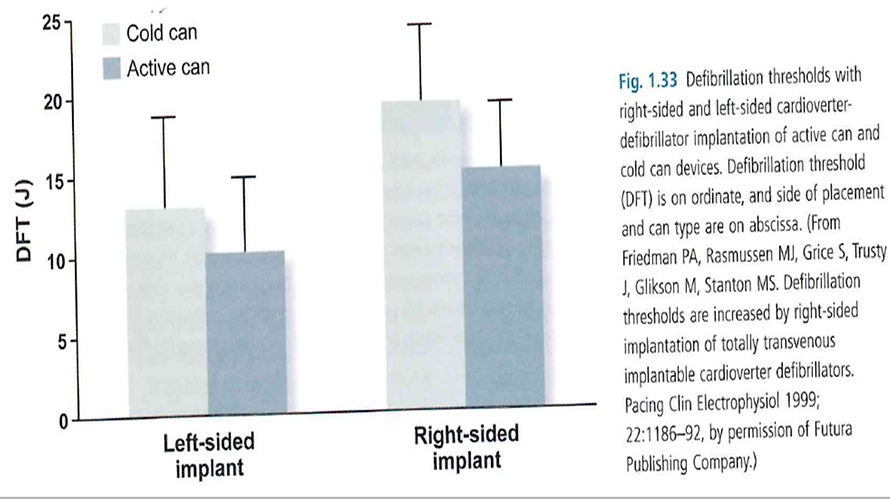
•Active vs cold can
Circulating pharmacologic agents
Poor lead placement/lead dislodgement
Cardiac disease
Hypoxia
Amplitude of VF waveform
Amplitude of VF waveform
Temperature
Body weight/body surface area
Low LVEF
LV dilatation/hypertrophy
Heart weight
Chronicity of leads
Circadian influence – 16% higher in morning compared with afternoon
gender
Clinical role of DFTs at implant
DFT testing determines the lowest energy that reliably defibrillates an individual patient
Benefits of DFT include
•Allowing a low first shock to be programmed
•Resulting in shorter charge time
•Battery preservation
•Lower risk of syncope
•MI
•post shock AV block
•myocardial damage and
•impaired sensing
DFT testing also allows for
•assessment of appropriate sensing of VF
•confirms integrity of system and
•establishes an adequate safety margin for defibrillation.
Reasons for DFT at implant
Children and young adults
Presence of congenital disease
Secondary prevention indication
Extreme LV enlargement
Clinical conditions that might have an increased risk of an elevated DFT
•HCM
•Channelopathies
•Arrhythmiogenic RV dyslphasia (ARVD)
non standard shock vector
•right sided or abdominal pulse generator
•unusual SVC coil position
Absolute contraindications of DFT testing
Risk of thromboembolism
•LA thrombus
•LV thrombus, nor organized
•AF in absence of anticoagulation
Inadequate anaesthesia or anaesthesia support
Known inadequate external defibrillation
Severe AS
Critical, nonrevasuclarised CAD with jeopardized myocardium
Hemodynamic instability requiring inotropic support
Relative contraindications of DFT testing
LV mural thrombus with adequate systemic anticoagulation
Questionable external defibrillation (massive obesity)
Severe unrevascularised CAD
Recent coronary stent
Hemodynamic stability
Recent stroke or TIA
Questionable stability of coronary venous lead
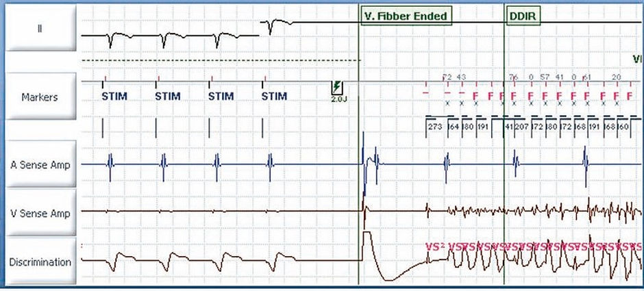
Induction techniques
Shock on T
A shock is delivered on the T wave (vulnerable period)
RV is paced at a fixed rate until a 1 - 2 J shock is delivered on the peak of the T wave, at a coupling interval of approximately 300 ms.
•The number of pulses is programmable between 2 and 25
•The cycle length between 100 and 800 ms
•The pacing amplitude at 5 or 7.5 V
•The coupling of the electrical shock between 20 and 600 ms
•The energy delivered between 0.1 and 36 J
DC fibber
DC FibberTM delivers a single 8 Volt direct current pulse through the high-voltage electrodes in order to induce VF.
Pulse duration: nominal 2 seconds (0.5…5 seconds)

Burst
Delivers bursts of stimuli at short cycle lengths with no extra stimuli.
Bursts can be delivered for an extended time by holding the Hold to Apply Burst button.
•Pulse amplitude: nominal 7,5 Volts (or 5 V)
•Pulse width: nominal 1,5 ms (or 1,0 ms)
•S1S1: nominal 30 ms (20 … 10 … 100 ms)

Assessing DFT techniques
One common technique – 2 VF inductions
1st shock: 10J < max device output ;
•if successful – approximate DFT is defined as this
If successful, next shock same energy programmed.
•If successful – DFT
Pts with an active can, pectoral, biphasic DFT <15J have a low risk of subsequent inadequate defibrillation and no additional testing may need to be performed.
In pts in whom the DFT approximation is higher, additional testing may be performed at implant or more commonly, annually until a chronically stable DFT is confirmed.
If 2 shocks 10J below the max device output are not achieved, system modification may be required.
Another technique is based on results of the Low Energy Safety Study (LESS) trial
Single conversion at 14J yielded a imilar +ve predictive accuracy (91%) as 2 successes at 17 or 21J, determining a successful outcome with a device that provided 31J.
The results were durable in that those pts whom a single VF induction was successfully terminated with 14J implantation, regardless of additional inductions, had similar long-term VF conversion success rates as all ICD recipients when the device was programmed to 31J.
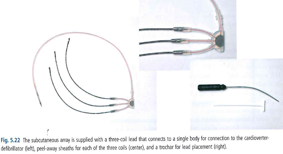
Management of pts with high DFTs
Add another lead
•Add a subcutaneous array or patch (7.3-9.5% complication rate- predominantly fracture)
•an azygous lead (lies directly behind LV)
•or CS coil to include more LV in defibrillation field
Use subcutaneous array- up to 3 coils
Move the generator to a left pectorial position if located on the right.
•In right sided devices, the proximal coil (SVC) tends to be inserted lower than a left sided device to get a smaller shock vector in a cold can.
1. RV: coil in lower SVC.
2. LV: coil in subclavian vein
Check for metabolic abnormalities or pneumothorax
Assess vector
•Insure RV lead is apical
•Exclude SVC coil if it is low I the RA or move it proximally
•Exclude the pulse generator with right sided implants – turn off
Reverse polarity
•Particularly if initial shock was not RV anode
•Or modify the waveform
Exchange the generator to a high output device
Add another lead


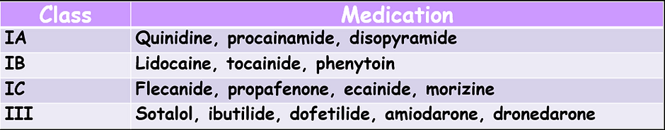
Membrane-active drugs
These agents may significantly affect defibrillator function, often mandating device testing on initiation