


Device specific algorithms
Summary
Abbott
•A Cap confirm
•Ventricular auto capture
•RV cap confirm and LV cap confirm
Biotronik
•Atrial capture test
•Ventricular capture test
Boston Scientific
•Right atrial automatic threshold (RAAT) – PPM only
•Right Ventricular automatic capture (RVAC) – PPM only
Pace Safe (RA, RV & LV in CRTs and ICDs)
Medtronic
•Atrial Capture management
•Ventricular Capture management
•Micra Ventricular capture management
•Left ventricular capture management
None are beat by beat capture
Microport
•Atrial Auto Threshold
•Ventricular Auto Threshold
Abbott
A cap confirm
A Cap Confirm only works with bipolar leads & looks at evoked response
NOT beat-by-beat
Once the automatic atrial pulse amplitude is adjusted, it will stay in effect until the next threshold search
Threshold searches are run every 8 or 24 hours, as programmed
The overdrive rate is determined using the average atrial sensed rate and variance
Starts at 0.5 above in-clinic previous threshold or 0.5 below programmed output, and decrements by -0.25 and then increased by +0.125V
Each pulse will be followed by a backup pulse (5V each – APP marker)
When back up pulse delivered AV delay will
•Decrese to 120 if programmed >120ms
•Increase to 100 if programmed <100ms
1.7x safety margin (see chart)
Rate must be <120 bpm


Ventricular auto capture
Beat-by-beat analysis
Evoked Response Detection:
•assesses capture by the evoke response.
•After an impulse is given, there is a blanking period (14ms) followed by a evoked response detection interval (46ms).
•If the device does not see an evoked response, the device will then send a backup safety pulse, a single output pulse at high settings to assure capture (4.5 V, 0.5 ms).


Fusion Avoidance
•To avoid threshold searches caused by fusion, the algorithm automatically extends the paced or sensed AV delay 100 ms on the next beat after non-capture to avoid fusion and allow intrinsic activity to come through.

Pseudofusion Avoidance
•To avoid threshold searches caused by pseudofusion, the algorithm automatically extends the paced or sensed AV delay 100 ms on the next beat after noncapture to avoid fusion, allow intrinsic activity to come through and results in a prolonged period (several complexes) of extended sensed AV delay.

Consecutive Non-capture
If two consecutive initial pulses indicate noncapture, then the amplitude is increased 0.25 V
•If capture occurs, the same amplitude is delivered in the next output to confirm capture
•If capture can be confirmed, a threshold search is initiated
•If capture cannot be confirmed the amplitude is increased one step at a time by 0.125 V until two consecutive captured beats occur
•If that happens, a threshold search is initiated
Threshold Search
The threshold search decreases the paced AV delay (to 50 ms) and the sensed AV delay (to 25 ms) to force pacing and minimize fusion. Threshold search occurs after two consecutive noncapture beats, every eight hours (automatic) and when magnet or telemetry wand is removed
•The pulse amplitude is decreased by 0.25 V two beats at a time until a loss of capture is observed for two beats
•At that point, the pulse amplitude is increased in smaller steps of 0.125 V at a time until capture is observed for two beats
•When the threshold is determined, the algorithm automatically adds 0.25 V to it


V auto cap set-up

Reviewing V auto cap
stable and appropriate trend

largely stable with some variation
consider performing a new autocap set-up

frequent out of range values resulting in high output mode
autocap should be turned off (or monitor only)

RV and LV cap confirm
Both based on evoked response
Back up pulse are for
•RV: after 90ms only when LOC is confirmed
•LV: after 80ms from the RV lead at all times
Not beat by beat
Can work with
•RV: ICD leads, integrated or bipolar
•LV: unipolar or bipolar
Starts at 0.5 above in-clinic previous threshold or 0.5 below programmed output, and decrements by -0.25 and then increased by +0.125V
Programmed 2x safety
Programming
A Cap confirm
Accessed from parameters; capture and sense; automatic capture settings
•A cap confirm: on monitor off
•Back-up pulse config: bipolar only
•Search interval: 8, 24 hours
V auto capture
Accessed from parameters; capture and sense; automatic capture settings
•V cap confirm: on off
•Backup pulse config: bipolar, unipolar
•Search interval: 8, 24 hours
•Paced/sensed AV delay 50/25, 100/70, 120/100
Warning: if in a single chamber mode (E.g., VVI/VVIR), hysteresis will automatically turn on


Biotronik
Atrial capture test
Based on atrial sensed beats
Starts at 3V
Drops by 0.6V until LOC for 2 beats
Goes up by 0.6V
Drops by 0.1V until LOC
Then checks again
Sets output 1V above threshold
Not beat by beat


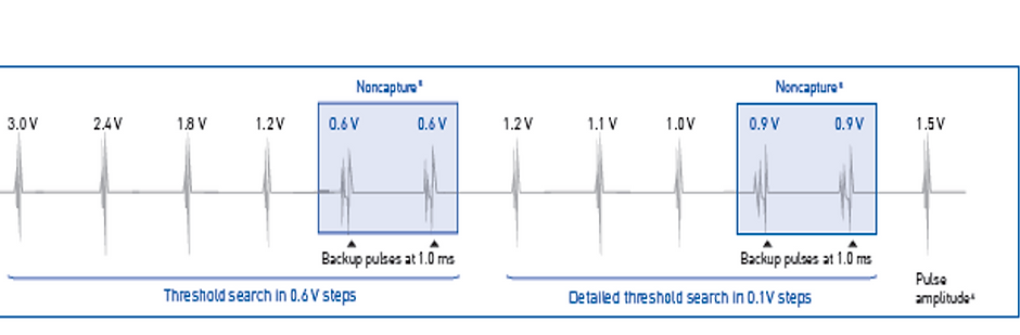
Ventricular capture test
Beat by beat capture
Based on evoked response
Starts at 3 V – analyses evoked response
Drops by 0.6V until LOC for 2 beats (provides safety pacing)
Goes up by 0.6V
Drops by 0.1V until LOC (provides safety pacing)
Sets output 0.5V above threshold


Programming
Accessed from Parameters; Bradycardia
•Capture Control: ON, OFF, ATM (monitoring only)
•Min Amplitude: 0.5, ....(0.1).... 4.8V, 1.0V
•Threshold Test start: 2.4, 3.0, 3.6, 4.2, 4.8V
•Safety Margin: 0.5, ...(0.1) .... 1.2V, 1.0V
•Search Type: Interval, time of day
•Interval (hour): 0.1, 0.3, 1, 3, 6, 12, 24
•Time of Day: 00:00, ...(10 min) ....23:50; 02:00


Boston Scientific
RAAT
Not beat by beat
required bipolar atrial lead
threshold tests are scheduled every 21 hours
evaluation of atrial capture is based on the presence of an atrial evoked response
amplitude is automatically adjusted to 2X the highest of the last 7 days with successful threshold tests at a non-programmable pulse width of 0.4 ms
the output is limited between 2.0 V and 5.0 V
Determining the RA pacing threshold
•evaluation of atrial capture is based on the presence of an atrial evoked response
•atrial pacing rate is based on the lower rate limit or the sensor rate and be increased by 10 bpm to ensure atrial pacing
•voltage decrements every 3 captured beats
•looks for 2 Loss of Capture (LOC) beats out of 4-beat moving window
•the second LOC in a 4-beat moving window is defined as “Confirmed LOC” (C-LOC)
•the threshold is defined as one voltage step higher than where C-LOC occurs
Adjusting the RA pacing output
•no beat to beat verification of atrial capture
•safety margin: amplitude 2X (non programmable) the highest of the last 7 measured thresholds
•non programmable pulse width: 0.4 ms
•maximal amplitude: 5.0 V
•minimal amplitude: 2.0 V
RVAC
RVAC is designed to dynamically adjust the right ventricular pacing output
ventricular voltage output is automatically adjusted to 0.5 V above the measured threshold
beat-to-beat verification of myocardial capture via sensing of ventricular evoked response
delivered output from a minimum of 0.7 V to a maximum of 3.5 V
the pulse width is non-programmable (0.4 ms)
in case of loss of capture, a back-up pacing pulse is delivered
when loss of capture is confirmed for two cycles out of four beats, automatic threshold test is initiated to check for the new threshold.
Determining the RV pacing threshold
•an automatic threshold test is systematically performed every 21 hours
•the test starts with an initialization phase (2 warm-up intervals to calibrate the assessment of the evoked response measurement followed by 12 intervals to initiate the evoked response channel filters)
•ER (evoked response) sensing is performed on a dedicated unipolar sense channel
•the ER channel uses lower frequency filters than those of the bipolar sensing channel (3-65 Hz versus 25-85 Hz).
•to assess the effectiveness of the capture, the maximum amplitude of the positive signal is evaluated in a window of 10 to 70 ms following pacing ambulatory threshold test
•amplitude starts at 3.5 V and steps down in 0.1 V increments
•throughout the threshold measurement, a backup pacing (BP) is systematically delivered after the first ventricular pacing (70 ms after the primary VP) at a maximal amplitude of 3.5 to 5 V to prevent any ventricular pause as a result of loss of capture
•voltage decrements every 3 captured beats
•looks for 2 Loss of Capture (LOC) beats out of 4-beat moving window
•the second LOC in a 4-beat moving window is defined as “Confirmed LOC” (C-LOC)
•the threshold is defined as one voltage step higher than where C-LOC occurs
•LOC at an amplitude > 3.0 V is considered an unsuccessful test
•if there is no capture at the initial amplitude or if 0.1 V is reached with no Confirmed LOC, the test fails
•an EGM is stored for the most recent ambulatory threshold test
Adjusting the RV pacing output
•amplitude is automatically adjusted to 0.5 V (non programmable) above the measured threshold
•the delivered output ranges from 0.7 to 3.5 V
•if any LOC occurs, a backup pace is delivered
•beat-to-beat capture verification using an evoked response channel
•new threshold measurement with adjustment of the delivered amplitude if the capture is ineffective
Pace Safe
For CRT and ICD devices
Not beat by beat
Output is set x2 for RA and RV
Output is programmable for LV (nominally +1V)
Threshold is adjusted every 21 hours
Trend review

Programming


Medtronic
Atrial Capture management
Automatically performs an atrial pacing threshold search by inserting test paces and observing for changes in the
•underlying sinus rhythm (Atrial Chamber Reset) and
•the timing of the ventricular response (AV Conduction method).
Atrial chamber reset
8 consecutive AS events are sensed:
•rate < 87 bpm
•sensor rate is less than the ADL rate
•No Mode Switch episodes
Atrial Pacing Test
•First test pace: 0.4 msec (PW) and amplitude at one setting below last measured threshold value, or 0.75 V if no previous search done:
•Amplitude decrements until 2 of 3 test paces indicated loss-of-capture (LOC).
•After LOC is detected, the amplitude setting is increased until capture (CAP) is confirmed for 3 consecutive test series.
Determining capture
•Atrial Chamber Reset Test Pace CAPTURE (no AR after test pulse)
•Atrial Chamber Reset Test Pace LOSS of CAPTURE (AR after test pulse)
AV conduction
Runs when stable intrinsic 1:1 AV conduction is observed with A pacing providing: (similar to AAI)
•In the stable rhythm test, 8 consecutive AP/VS events occur and
•the max AV interval is <296ms
Atrial Pacing Test
•To achieve a consistent AP-VS pattern during test execution, the test is performed by increasing the AP rate by 15 ppm & increasing the Paced AV delay to 383ms.
• After three lead in pulses, a test pulse is delivered, with a backup pulse delivered 70ms later at the normal programmed output and 1.0ms pulse width.
•For patients with no underlying sinus rhythm, but with intact 1:1 AV conduction, a capture test pace will cause a VS to occur within a specific “window,” based upon measured intrinsic PR conduction times.
•If a test pace fails to capture, a backup pace (at higher output settings) will cause the VS event to occur during a secondary “window” of time.
•Test pace starts at 0.4ms pulse width with amplitude the programmed output and decremented down by 0.125V. If threshold higher than programmed output, output is increased till capture is achieved by 0.125V
•Amplitude decrement until 2/3 test paces indicate LOC
•Capture confirmed when 3 consecutive test paces capture


Ventricular Capture management
Step 1: At rest check
Nominally, the ventricular threshold is measured once a day at rest. Before the pacing threshold search can begin, the device must first determine that the conditions are right to carry out the test.
For a Pacing Threshold Search to go ahead, the pacemaker monitors 8 cycles to ensure conditions are favorable, that is:
•No more than 2 out of 8 beats can be at greater than 95bpm.
•The sensor rate less must be less than the ADL rate, and
•at least one valid AV interval has to occur during the eight intervals
Step 2: Pacing Threshold Search
S = Support Cycles - at programmed amplitude and pulse width
T = Test Paces - test amplitude and pulse width (AV delay at test = programmed AV delay-15ms)
B = Backup Paces - follows T by 110 ms at programmed amplitude and 1.0 ms pulse width
Of the series of 3
•2 captured beats determines output is above threshold
•2 loss of captures determines output is below threshold

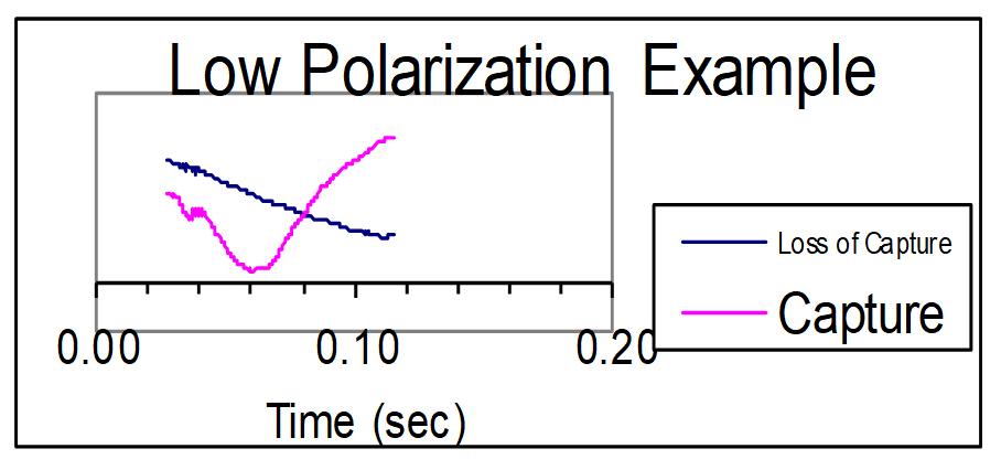
Step 3: Evoked Response Detection
Determined by slew rate.
The slew rate for Loss of Capture is always negative, whereas that for capture changes direction.
Secondly, there is a sharper drop that starts to occur at about 40 ms.
A sharper drop in slew rate marks capture, as opposed to a less precipitous line that shows loss of capture

Amplitude Test
a) Test amplitude starts at current programmed output
b) Pulse Width is set at 0.4 ms
c) Amplitude is reduced by one setting (-.0125V) and series is repeated until LOC
d) Amplitude is increased until capture is regained (+0.125V) (Threshold)
Pulse Width Test
a) The test pulse width is set at the last pulse width from the previous search or at 0.21ms if no previous
b) Amplitude is set at two times the amplitude threshold determined during the Amplitude search
c) The upper Pulse Width limit for the test pulse is 0.4 ms
d) The Pulse Width setting that is in operation when capture is recovered at two times the amplitude threshold is designated the pulse width threshold.
Micra Ventricular capture management
Overall very similar to RV capture management
a pacing threshold search is initiated at 12:00 midnight each day and the device retries each hour if a search cannot be completed.
Additionally, when Capture Management is programmed to Adaptive, Micra verifies that the ventricular amplitude is safely above the ventricular threshold each hour throughout the day.
No backup paces are delivered in Micra. Instead, the pacing interval after a loss-of-capture is overdriven to minimize the pause between heart beats.
Ventricular Capture Management for Micra TPS is only able to run if the pulse width is 0.24 ms or 0.4 ms. The pulse width is not modified by VCM for Micra TPS.
Amplitude is adapted only when a pacing threshold search is successful; otherwise, it remains as programmed (nominally 0.24ms).
In Micra, the target amplitude is based on the highest pacing threshold recorded in the prior 14 days.
In Micra TPS, the High Thresholds Condition warning is issued if the amplitude threshold is greater than 5.0 V. Micra responds by adapting to an Amplitude of 5.0 V at the programmed pulse width.
In Micra, a safety margin (acute phase is + 1.5 V and chronic phase, + 0.5 V is nominal) is added to the target threshold to determine the Amplitude.
The maximum Amplitude is 5.0 V.

Left ventricular capture management
When LVCM is programmed to the Adaptive setting, the device uses the LV pacing threshold to adjust the pacing amplitude toward the target amplitude.
The target amplitude is based on the programmed settings for LV Amplitude Safety Margin &LV Maximum Adapted Amplitude parameters.
The LVCM test occurs every day at 1:00 am if the patient’s rhythm is stable enough to support a pacing threshold search. Conditions such as programmed LV output greater than 6 V, unstable patient rhythm (R-R variability > 200 ms) or arrhythmia, or heart rate greater than 90 bpm are considered unstable.
If stability checks are unsuccessful, the device automatically continues to schedule searches every 30 minutes.
The LVCM test looks for an RV sense in one of two locations to determine capture:
•When an LV-only pace is delivered and an RV sense is detected shortly after the LV pace (V to V conduction), capture is confirmed.
•When an LV-only pace is delivered and a RV sense is detected at the intrinsic AV interval (conduction from atrial pace or sense), noncapture is confirmed.
•Note: no backup V pacing w LOC


As a baseline, the LVCM algorithm measures both the AP to RVS conduction time and the LVP to RVS conduction time to determine the windows in which an LV pace will conduct to the RV (capture) and in which the atrial event will conduct to the RV (noncapture).
The device then conducts a pacing threshold search to determine the LV pacing amplitude threshold at the programmed pulse width. LVCM varies the amplitude of test paces (by 0.125 V) to find the lowest amplitude that consistently captures the left ventricular myocardium.
The device evaluates capture by observing the timing of sensed RV events following an LV paced event to determine whether test amplitudes result in capture.
In each threshold measurement, three support cycles precede the test pace to maintain pacing support during the pacing threshold search.
During the test pace, the ventricular pacing configuration changes to LV-only. If the left ventricle responds to a test pace, the result is “capture.”
If no response is detected, the result is “loss-of-capture.” The result of a test pace is ignored if the device cannot determine whether the test pace captures the myocardium.
In the graphic below, you can see that during loss of capture, the RV sense occurs later (due to AV conduction) and during capture, the RV sense occurs shortly after the LV pace (due to V-V conduction).
If LVCM is programmed to the Adaptive setting, the device calculates a target amplitude by adding the programmed LV Amplitude Safety Margin to the calculated amplitude threshold. If the target amplitude is lower than the current pacing output, the device reduces the amplitude by 0.25 V every other day until it reaches the target amplitude.
There is no programmable lower limit and the pulse width remains at the permanently programmed pulse width.
If the current amplitude threshold is higher than the last measured amplitude threshold, the device immediately adjusts the operating amplitude to the target and rounds it up to the nearest 0.25 V.
If the target amplitude is greater than the LV Maximum Adapted Amplitude, the LV Amplitude will be adjusted to the Maximum Adapted Amplitude at the programmed pulse width.
Programming
Accessed from parameters; leads; capture management
•Capture management: adaptive, monitor only, off
•Amplitude margin: 1.5x, 2x, 2.5x, 3x, 4x
•Minimum adapted amplitude: 0.5, 0.75, ...; 1.5 (atrial), 1.75, 2.0 (ventricle), ... 3.5V
Accessed from additional parameters
•Capture test frequency: 15 min, 30 min, 1, 2, 4, 8, 12 hours, day at rest (ventricular), Day at time (e.g., 1:00AM (atrial), 7 days at time
•Acute phase days remaining: off, 7, 14, .., 84, 112, 140,.., 252 days
•V. Sensing during search: Unipolar, bipolar, adaptive


Microport
Atrial auto threshold
The device selects one of the following 2 methods, to evaluate atrial capture based on the patient’s rhythm at the time of the pacing threshold search
•P test and
•AR test
RAAT is launched every night at 1:00 am
a selection phase is required to identify which test will be used
P test runs during normal stable sinus rhythm; atrial threshold is measured by increasing the pacing voltage
AR test runs when stable 1:1 AV conduction is observed with atrial pacing; atrial threshold is measured by decreasing the pacing voltage

P test
•The P test is launched if the device has detected 6 PP intervals (7 P waves) over the last 8 cycles and the PP intervals are stable (<16 ms).
•overdriving of the atrial rate
•progressive increase of the atrial pacing amplitude (steps of 0.25 V)
•the diagnosis of atrial capture/non capture is based on the absence/presence of a sensed atrial signal following atrial pacing
•if there is one As after Ap: no atrial capture
•if there is no As after Ap: atrial capture

In order to check if the atrial spike is efficient (capture), the device calculates the PP stability window (PP average +/- 8 ms).
For each tested amplitude:
•the device senses 3 atrial signals that have to be within the stability window
•it delivers atrial pacing (spontaneous atrial rate – 200 ms to overdrive sinus rhythm)
•if an atrial signal is detected within the stability window: diagnosis of non capture and increase of the amplitude by 0.25 V steps
•if no atrial signal is detected within the stability window: diagnosis of capture; if a second capture occurs at the same amplitude, the test value corresponds to the atrial threshold

AR test
•The device verifies the presence of a stable 1:1 AV conduction by prolonging the AV delay (450 ms) during 10 cycles (2 first cycles of transition).
•progressive decrease in the atrial pacing amplitude
•the diagnosis of atrial capture/non capture is based on the absence/presence of a sensed ventricular signal following atrial pacing
•if there is one R wave (Vs) after Ap: capture
•if there is no R wave (Vs) after Ap: no capture (atrial back-up pacing)

Adjustment of the amplitude
•the minimum atrial amplitude is programmable
•automatic adjustment of the atrial pacing amplitude: measured atrial threshold + 1 V
•if the measured threshold is > 3 V, the amplitude is automatically programmed to 5 V and RAAT is switched to OFF
•if RAAT cannot be measured, the device takes the same value as the day before
•if RAAT cannot be measured during more than 7 consecutive days, the atrial amplitude is programmed to the Safety atrial amplitude (programmable, nominal 3.5 V)
Ventricular Auto Threshold
The Ventricular Autothreshold function is available in all pacing modes, which provide ventricular pacing except in SafeR mode.
•periodical measurement (6 hours, 4 times a day) of the ventricular pacing threshold
•automatic adjustment of the ventricular pacing amplitude to provide a 100% safety margin for the next 6 hours
•no beat to beat verification of capture efficiency
•a minimum ventricular amplitude is programmable
Note: will only work on thresholds <2V
Periodical measurement of the ventricular threshold
The automatic threshold test sequence is automatically launched:
•every 6 hours
•after a ventricular manual threshold test
•after reprogramming of the auto threshold function from OFF to “MONITOR” or AUTO
Waiting phase
•8 cardiac cycles are delivered at the current pacing rate.
•ventricular amplitude programmed at 5 V (programmed pulse width)
•the calibration phase can start if there is efficient ventricular capture at 5V and if the ventricular rate is < 95 bpm
•after a magnet test
•after programming of the V pulse width and V pacing polarity

Calibration phase: The calibration phase is required to demonstrate an appropriate differentiation of the evoked potential response (EPR) and of the post-pacing polarization of the electrode. The signal is analyzed in a window of 64 ms following ventricular pacing.
•capture: post-pacing polarization+ evoked response
•non capture: post-pacing polarization
To reduce the risk of fusion beats during the calibration phase and the threshold test:
•the AV delay is shortened by 65 ms in DDD or VDD
•the escape interval is shortened by 65 ms in VVI, DDI and fallback mode switch
During the calibration phase, different pacing amplitudes are delivered:
•3 ventricular stimuli at 4 V (programmed pulse width): first stimulus to avoid Wedensky effect; calibration on the 2 following spikes with evaluation of the signal in a 65 ms window; average of the 2 measurements
•3 ventricular stimuli at 2 V + safety pulse at 2.5 V/1 ms: first stimulus to avoid Wedensky effect; calibration on the 2 following spikes with evaluation of the signal in a 65 ms window; average of the 2 measurements
•comparison of the average measurements at 4V and 2V to demonstrate similar evoked response
•3 ventricular stimuli at “0” V + safety pulse: to better detect possible fusions beats; if the device detects a signal after a 0 V stimulus, diagnosis of fusion beat; a second calibration is performed
The calibration phase fails when:
•diagnosis of fusion beats (even after the second calibration)
•excessive polarization (poor ratio evoked response/polarization)
•pacing threshold higher than 2 V
•If the calibration phase fails, the ventricular amplitude is set to 5 V and test restarts 6 hours later.

Threshold test
•The threshold test is performed at the programmed pulse width and pacing polarity.
•steps of 0.2 V
•threshold test stops after a loss of capture or at the amplitude of 0.2 V
•after a loss of capture, a safety pulse is delivered after 65 ms (amplitude 2.5 V, pulse width 1 ms)
Adjustment of the amplitude
•the minimum ventricular amplitude is 1.5 V (programmable)
•automatic adjustment of the ventricular pacing amplitude to provide a 100% safety margin for the next 6 hours (measured threshold x 2)

Variations in trends
The top image represents a stable threshold trend
The bottom image represents a mostly stable trend with some incorrect high output modes

Programming
Accessed from parameters; special functions
•Auto Threshold: on, monitor, off
•Minimum adapted amplitude: 1.5 (A), 2, 2.5(V), to 5V
•Safety atrial amplitude: 3.5(A), 5(V)
•Atrial max rate
(for A only or V in single chamber): 75, 80, 85, 90, 95, 100, 110
